Lean-to Rigging Beam
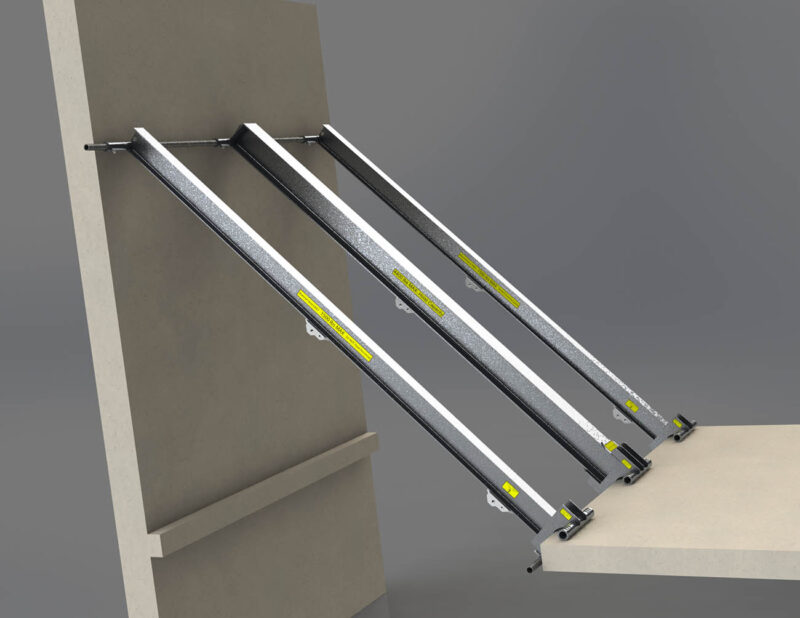
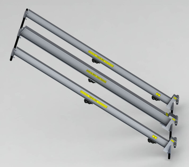
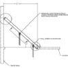
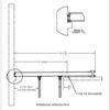
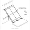
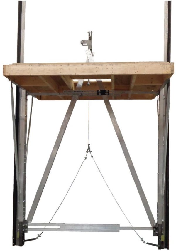
Spider’s Lean-to rigging device is designed to provide temporary rigging points in elevator shafts where other rigging options are not available. The three beams work in conjunction to lean against the back wall of an elevator shaft, providing anchor points for a false car or car sling, independent fall arrests, and lifting/positioning of guide rails.
Specifications
| Part Number | Description | Personnel Hoist Capacity | Fall Arrest Capacity |
|---|---|---|---|
| 720793-1 | Lean-to rigging assembly | 4,400 lb/beam (1,996 kg/beam) | 2 X 5,000 lb (2,268 kg) anchor per beam |
Requirements
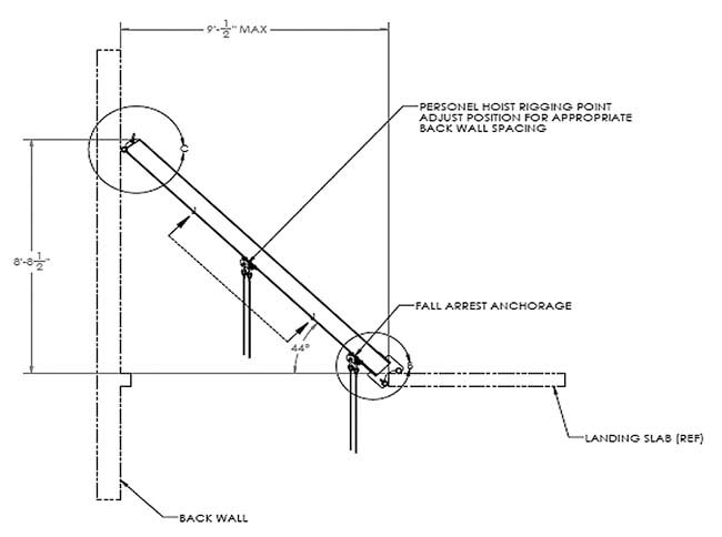
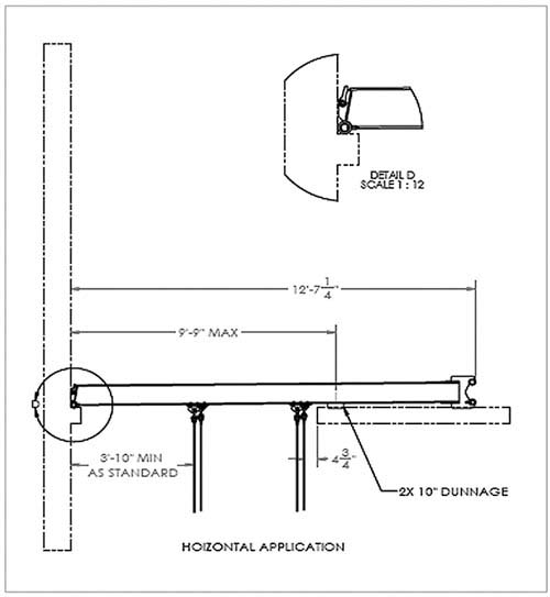
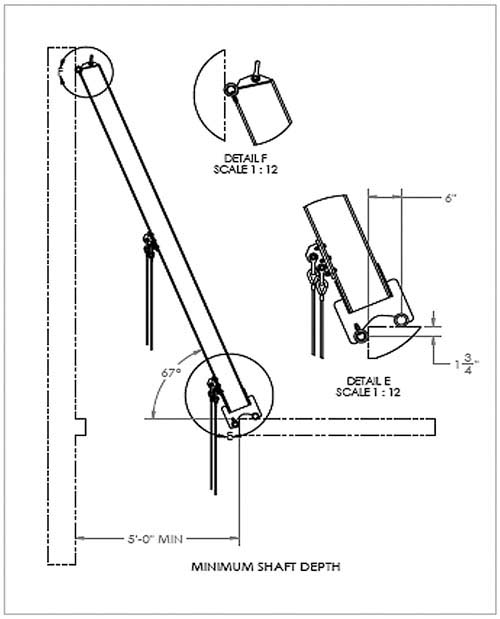
- Minimum shaft span: 5 ft (1,524 mm)
- Maximum shaft span: 9 ft 0.5 in. (2,756 mm)
- Slotted holes at the base of each beam allow the beam to be anchored in place to the concrete deck. Two 3/8” (0.95 cm) diameter fasteners are required per beam.
- Tieback cables are required.
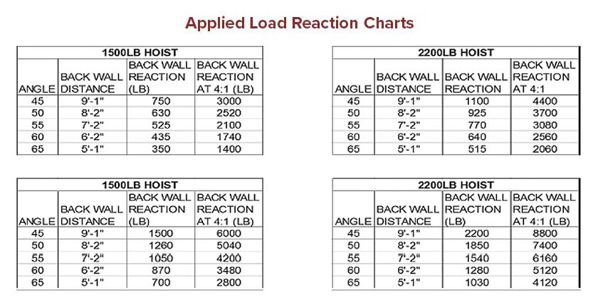
- Supporting structure shall hold 4x loads indicated without failure. Capacity shall be determined by a qualified person. (Refer to Applied Load Reaction Charts below.)
Key Features
- The center beam acts as a support structure for hanging a suspended scaffold suspension wire rope to lift either a false car or car sling.
- The outer two beams serve a dual purpose:
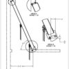
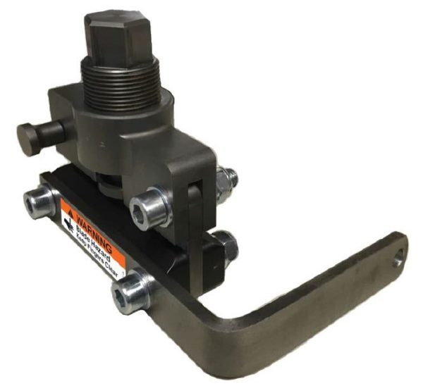
- Each beam is equipped with an adjustable anchor point designed to act as an independent fall arrest anchor.
- Fall arrest anchor point adjustability: 6”-12” from base (15.2 cm – 30.5 cm)
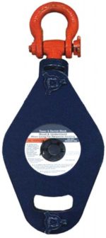
- Located near the center point is another adjustable anchor point from which a pulley can be hung to help lift and position the elevator guide rails.
- A unique base on each beam helps transfer the load to the concrete slab. Each beam is equipped with hoisting points at the top to help lift them into position.
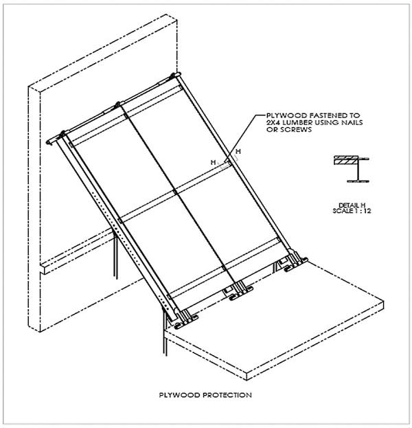
- With the addition of plywood, the lean-to beams can also provide overhead protection.
Talk to a specialist
"*" indicates required fields


